|
|
Joachim Schlosser: Development and Verification of fast C/C++ Simulation Models for the Star12 Microcontroller
The architecture, the OMI is founded on, defines the Open Model Interface to be the linkage between an application and one or more model managers. An application can be a debugger or simulator front-end, basically a software tool that uses a number of models.
A model in OMI context is a “tailorable, functional representation” ([IEE99, p. 3]) of a VC, not a stand-alone application but a component delivered in object code format to ensure intellectual property protection. The model may cover aspects of specification that can be simulated as well as timing information and physical characteristics. All data related to the VC can be integrated into the model. Usually a model is customized and then incorporated one or more times into a complete system, it is then called a model instance. So a model can have any number of instances associated with it.
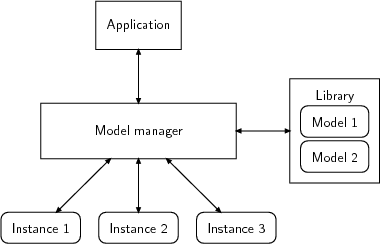
The application using the models can be specialized to a simulator, adding the capability of simulating the behavior of a hardware or system design. The OMI models do not interact directly with the application; they are integrated into a model manager, which coordinates interactions. In Figure 2.13 on page 71 the structure is visualized. A model and its instances are associated to exactly one model manager. A model manager manages any number of models. An application uses one or more model managers. A model manager is used by only one application. The interface between application and model manager is the OMI, as mentioned before.
|
|
It is essential that an application never directly calls a model routine, as the model manager may run private communication with internal services like error handling.
Models do not necessarily be delivered as single parts, they can be collected to form a model library, controlled by a common model manager, as shown in Figure 2.14 on page 74. For model usage it does not matter whether it is part of a library or not. The same way it is possible to deliver the OMI software elements as a monolithic block, e. g. a model that includes its own model manager.
|
|
The lines between the elements in the two figures have arrows on both ends, indicating that information flows in both directions at each connection. Especially at the OMI boundary this means that the standard defines function calls across the interface go in both directions, resulting in an application part and a model manager part of OMI.
As models can be implemented using a variety of languages, the IEEE standard uses the general term modeling language for all languages that are used to develop OMI models. The compiler, which produces the object code representation from a high-level modeling language like a HDL, is called a model compiler. So for example a VHDL or Verilog design is fed into a model compiler to get object code, whereas with C code a normal C compiler is sufficient.
An OMI model package contains a so-called bootstrap file besides the dynamically loadable model manager object file. The only global symbol the object file may define is the omiBootstrapRoutineT function. The bootstrap file is needed by the application to bootstrap the model manager it is associated to, it gives information on the location-independent name of the model manager object file and the C name of the bootstrap routine for the model manager. The file contents looks like this:
MANAGER: vendorX_MODELMANAGER_1.0.so
BOOTSTRAP: vendorX_bootstrap_1_0
An OMI application can be specified using two key characteristics, presented in detail in [IEE99], section 4.3 on pages 8-9. The terms “port”, “viewport” and “parameter” are explained in detail in the subsequent section 2.2.2 on page 78.
The application characteristics are vital to the simulation environment as they may narrow the bunch of fitting model managers.
It is required that an OMI-compliant simulator – remember a simulator being a special type of application – at least supports the two-state model boundary class and the cycle-based simulation style. An OMI event-based simulator is a different kind of OMI-compliant simulator that supports at least the simple-logic model boundary class and the event-driven simulation style.
The model or model manager determines the characteristics of the application and diagnoses incompatibilities between them and its own requirements or those of the models. The information gained can be used to auto-reconfigure the model manager or model to the simulation environment provided by the application during the bootstrap process.
Execution is activity – calls to OMI routines – during an OMI session driven by an application and one or more model managers. Simulation is a primary kind of execution but not the only one. One could think of an execution that only extracts timing information. Of course the execution proceeds on an orderly fashion, separated into three sessions and five stages, presented in order of occurrence:
All stages can directly lead to the fifth stage, Termination, without executing the following stages, making it the final stage in every case.